TRIUMPH ROCKET 3
Table of Contents

For Rocket III Touring with single headlight:
Go to the H4 Page here and order the H4 Single ‘In Shell’ Headight Relay Kit. You can also order the LO Beam Cut option for that Kit on the same page.

Both bulb leads longer (puts relays under front of gas tank)H4 Sockets left off for easier shell insertion
H4 Dual Headlight Relay Kit – [ In Bucket ]
This kit helps reduce loading on the stock switch and connectors and increases the voltage ( hence brightness ) of your headlights. Quality componts made to last.
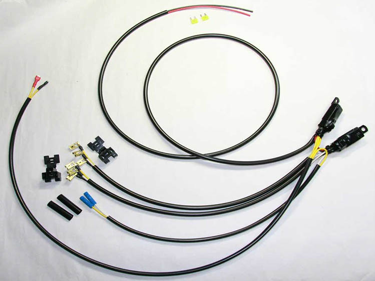
H4 Dual Relay Kit for Rocket III w/Lo Cut
Fuse panel Connection option.
Main lead wires are longer and sheathed to 6 in (15 cm) from ends.

Triumph Rocket 3 PC-8 with Relay Kit
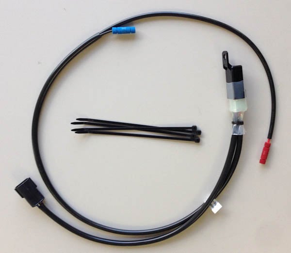
Triumph Heated Grips Relay Kit
This Kit plugs into the stock connector and provides switched power and ground for your heated grips. Please read the notes at the bottom carefully before buying this Kit. I have been told that the 2014 triumph Explorer XC does not fit this Kit. The heated grip connector should be a 3 pin connector to fit the one shown below.
The connector used for this Kit is an Amp Econo-Seal Male 3P, also available separately
INSTALL NOTES:
– The connector plugs into the heated grip connector on the bike. You may have to remove the dummy connector first.
– The posilocks supply your heated grips main power and ground inputs, red is POS, blue is NEG.
PLEASE NOTE: It has come to light that some Triumphs were wired incorrectly, with reversed postions of the hot leads in the bike’s heated grip connector. You might have to swap the hot terminals in the Eco-S connector. First, check your battery draw when bike is off. It should be 100-150 MilliAmps if you have an onboard clock. If you have a security system, that will also draw some power. The idea here is to note any increase in battery current draw after plugging in this Kit to the bike. Pull the fuse on the security system to make it easier to check any unwanted battery draw.
Battery Drain Test:
First you need a VOM. Plug in the leads so that it will measure HIGH Amps. That should be 10A or more. Set the VOM to the HIGH Amp setting but don’t turn it on yet. Now, disconnect your NEG battery terminal(s) and move them away from the battery post enough that they don’t touch the post. Connect the black VOM lead to the battery post and red lead to the terminal(s) you just removed. Make sure the NEG terminals don’t touch the battery NEG post. If there’s more than one terminal you can use the battery post screw and nut to combine them. You will be measuring all current between the post and NEG terminals.
Now turn on the VOM. You will see whatever battery current drain on the display, that is normal for your bike. Record this setting so you don’t forget. Simply put, measure and record your bike’s normal battery current draw.
Now plug in the Kit and note and record any significant increase. If you haven’t installed any heated grips yet, just make sure the Kit’s output leads aren’t touching any live wires. There should be no additional current draw if the Kit is correctly pin matched in the connector. If there is an increase of more than 10 MilliAmps, and when you unplug the Kit the battery goes back to normal current drain, then you will need to swap the pins as outlined below.
And of course after swapping the pins in the Kit’s connector, you should recheck the battery drain to be sure that there is no additional drain from the Kit. Once you are sure of correct pin configuration you should complete the instal of the heated grips and recheck battery drain.
Here’s how to swap the terminals (purple and blue wires in 3P connector)
What you’ll be doing is leaving the black wire in place and pulling out the blue and purple(red) wire terminals, then swap their positions and reinsert. Note orientation when removing and reinsert the same way. The seals will remain in place.
1 – remove the yellow retainer with a small flat blade driver – pry using the slots, it will pop loose – remove it
2 – insert the blade next to the terminal of the blue wire (on open side) and pry away from terminal while pulling the wire enough to release the terminal back out of the housing – there is a small plastic tab in there you need to pry back, be gentle
3 – do both blue and purple wires, then reinsert blue where purple was, and purple where blue was
4 – push back in the yellow retainer – it will only fit one way – then push it in until it clicks into place with needle nose pliers etc.
Additional Notes:
I have configured this Kit so that I think it will work on most Triumphs. Very few should have to swap pins. I’m sorry but there’s no way for me to know for sure which years and models are configured differently. It seems that the factory wired some bikes differently by mistake. But at this time I’m sorry to say that you MUST TEST your bike to be sure, or your battery might lose its charge over time when the bike is not being used regularly.
Also, those who have purchased this Kit previously should do the battery drain test to ensure their Kit is setup right. If you ride regularly you might not notice the small battery drain when the Kit is configured incorrectly. This battery drain test is good to know how to do for future diagnosis so take the time to learn and do it right.